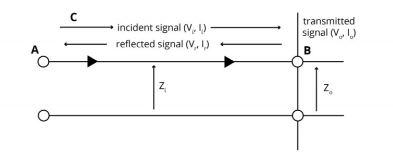
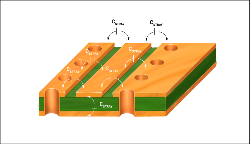
We previously discussed impedance discontinuity and signal reflection in our PCB transmission line series. Reflections occur due to impedance discontinuity.| Sierra Circuits
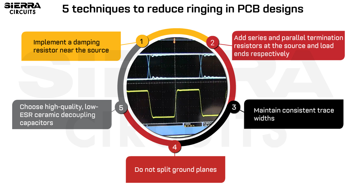
To reduce PCB ringing, implement a damping resistor at the source and maintain uniform trace width and spacing throughout the signal line.| Sierra Circuits
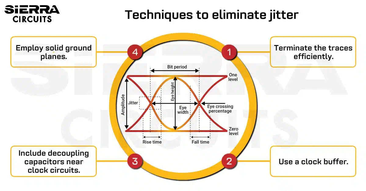
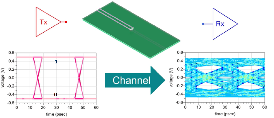
High clock frequencies and decreased rise times are some of the effects of high-speed signals in a PCB design, leading to signal degradation.| Sierra Circuits
Signal integrity is the measurement of a signal’s quality when it propagates from the transmitter to the receiver in an electronic system.| Sierra Circuits
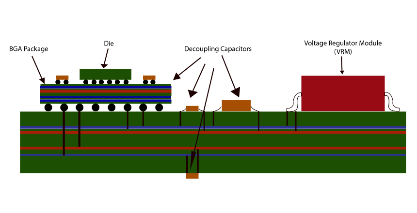
Power integrity is one of the mind-boggling subjects when it comes to PCB designing. In this blog, we try to explain power integrity basics.| Sierra Circuits
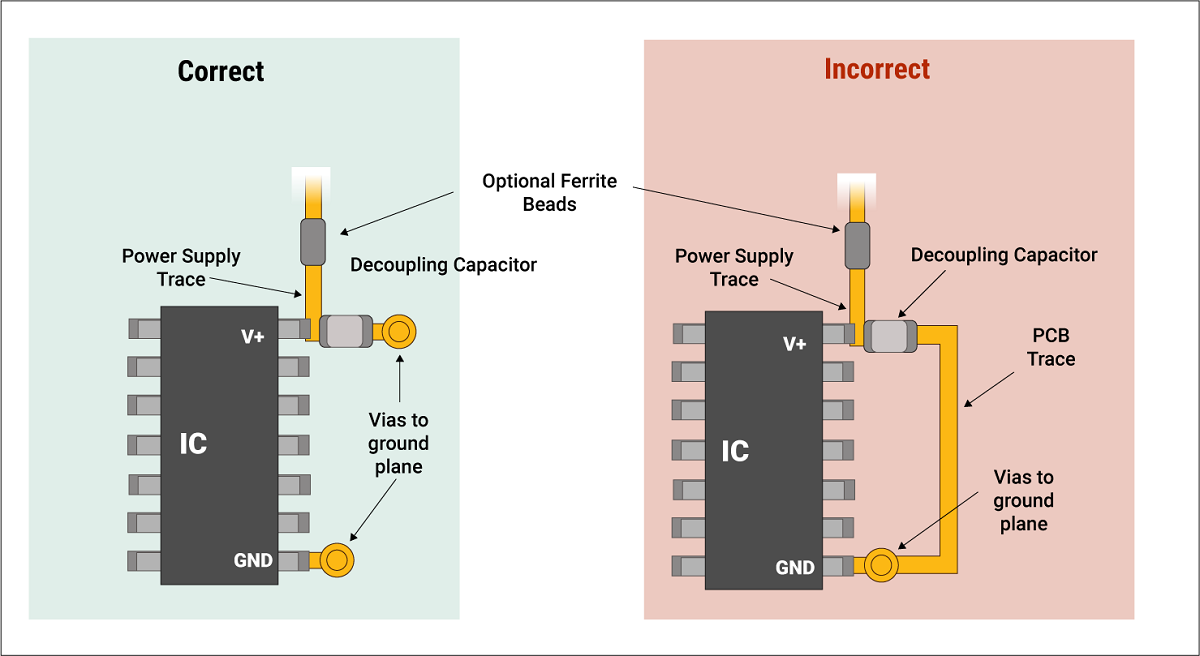
Placement of a decoupling capacitor or bypass capacitor is critical as it provides high transient currents to an IC to reduce power ripples.| Sierra Circuits